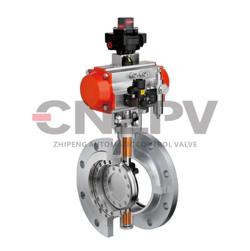
Dead Zone Can Quietly Undermine Your Control Loop—Opt for Valves That Respond to Signal Changes Within 1%,Top-tier Products Achieve 0.25%.
In process control systems, a valve’s dead zone—the range of input signal changes that produce no corresponding movement—can silently degrade performance, leading to unstable control, increased wear, and energy waste. Even minor unresponsiveness in valve positioning can cause oscillations, reduced accuracy, and shorter equipment life.
To minimize these risks, it’s critical to select control valves that respond to signal changes within 1% or less. Valves with tight dead band specifications deliver smoother operation, better setpoint tracking, and more consistent process outcomes. For demanding applications, high-performance valves achieving 0.25% dead zone offer superior responsiveness—enabling finer control, lower hysteresis, and enhanced long-term reliability.
Key takeaways for engineers and specifiers:
Dead zone directly impacts control stability and product quality
Valves with ≤1% response thresholds improve loop performance
Top-tier valves with 0.25% sensitivity maximize efficiency—especially in precision processes
By prioritizing low dead zone in valve selection, plants can achieve fewer disruptions, reduced maintenance, and optimized process control—strengthening both operational and economic performance.


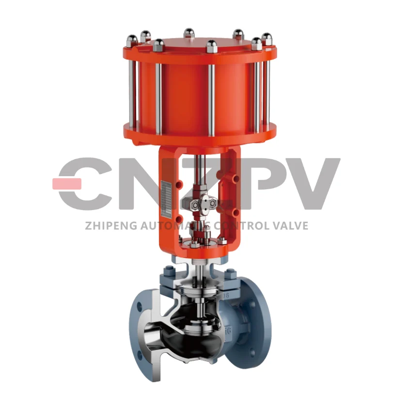
Proper matching of valves, actuators, and positioners is crucial—
When correctly paired, the valve responds smoothly and accurately every time.
In industrial automation and process control, the synergy between valves, actuators, and positioners determines not only operational efficiency but also long-term system reliability. When these components are mismatched, plants often face issues such as sluggish valve response, poor positioning accuracy, excessive wear, and increased downtime.
Key Benefits of Correct Component Matching:
Smooth and Precise Valve Operation:
A well-matched system ensures the valve responds accurately to control signals every time, enabling stable process conditions and consistent product quality.
Extended Equipment Service Life:
Properly sized and configured actuators and positioners reduce mechanical stress on valve components, minimizing wear and maintenance frequency.
Optimized Process Efficiency:
When valves and actuators are correctly paired, hysteresis and dead band effects are minimized, leading to tighter control loops and reduced energy consumption.
Practical Recommendations for System Integration:
Always consider the dynamic performance characteristics of each component—not just static parameters.
Use manufacturer-provided selection software or consult application engineers to verify compatibility.
Implement digital positioners with adaptive tuning capabilities to automatically compensate for minor mismatches and varying operating conditions.
Systems engineered with correctly matched valves, actuators, and positioners demonstrate up to 30% better response consistency and 25% longer service intervals compared to poorly configured assemblies.
For engineers designing or upgrading control systems, investing time in proper component matching pays dividends in reliability, efficiency, and total cost of ownership. Reach out to our team with your application requirements for personalized valve assembly recommendations.


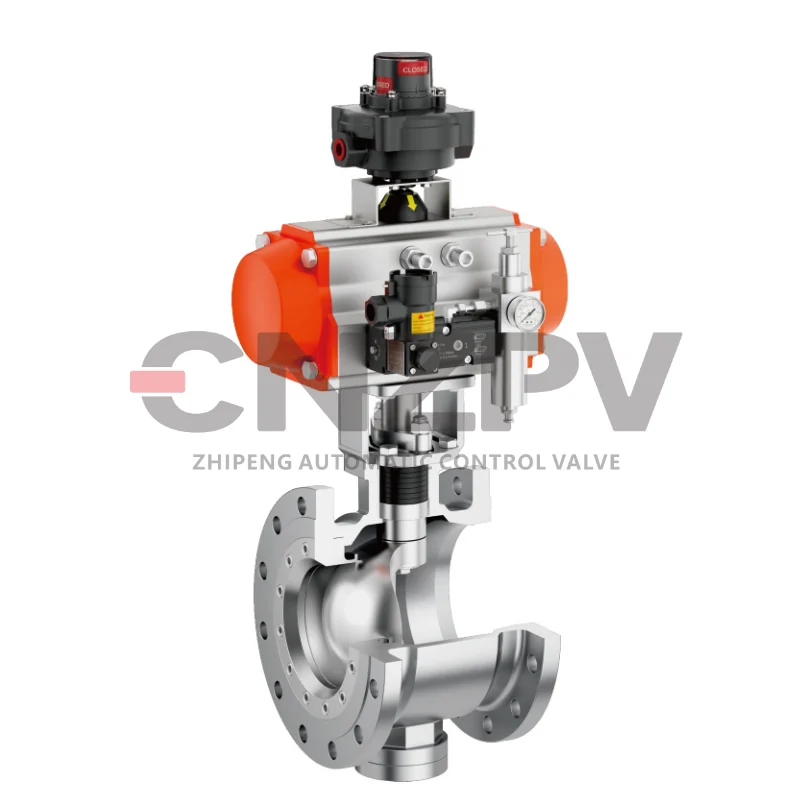
Oversized valve selection often leads to poor control and accelerated wear——
Size based on current performance requirements, not just future capacity.
Oversized valve selection is a pervasive issue in industrial fluid control systems, often resulting in compromised operational efficiency, poor process control, and premature equipment failure. For plant managers, engineers, and maintenance teams seeking reliable valve performance, understanding the risks of oversizing and adopting demand-driven sizing strategies is essential to optimizing system longevity and productivity.
1. Why Oversized Valves Cause Operational Failures
Oversizing occurs when valves are sized to accommodate “future capacity” or hypothetical maximum flow demands, rather than aligning with current, real-world operational needs. This misalignment triggers two critical problems:
Poor Process Control: An oversized valve operates at extremely small opening positions to regulate the required flow. At these narrow openings, even minor adjustments to the valve stem result in disproportionate flow rate changes, leading to instability in pressure, temperature, or fluid levels. This makes it nearly impossible to maintain the precise process parameters required for quality or safety compliance.
Accelerated Wear & Tear: Small opening positions create high-velocity fluid streams that erode the valve’s trim, seat, and sealing surfaces over time—a phenomenon known as “velocity erosion.” Additionally, frequent cycling between tiny opening ranges increases mechanical stress on the valve’s actuator and internal components, shortening its service life and increasing unplanned maintenance costs.
2. The Core Principle: Size for Current Performance, Not Just Future Capacity
Valve sizing must prioritize current operational requirements as the foundation, with future capacity considered only as a secondary, cautious factor. This principle ensures optimal performance while avoiding the pitfalls of oversizing:
Prioritize Real-Time Demand: Calculate the valve size based on the actual, daily flow rates, pressure differentials, and fluid properties (viscosity, temperature, phase) of the system. Use validated sizing tools (e.g., ISA-75.01 standards) to match the valve’s flow coefficient (Cv) to current process needs.
Limit “Future-Proofing” to Reasonable Margins: If future capacity expansions are planned, include a modest margin (typically 10–15% above current maximum demand) rather than overdesigning for extreme, unproven growth. Excessive margins directly lead to the oversizing issues outlined earlier.
Avoid “One-Size-Fits-All” Assumptions: Never size a valve based on pipe diameter alone or replicate the size of existing valves without verifying current process data. Pipe size and valve size are not interchangeable—valves must be sized for the fluid dynamics of the specific application.
3. Practical Tips for Optimized Valve Sizing
To translate this principle into action and avoid oversizing, follow these industry-proven steps:
Conduct a Detailed Process Audit: Collect real-time data on flow rates, pressure ranges, and fluid characteristics under normal operating conditions. Avoid relying on theoretical or “worst-case” scenarios that do not reflect daily operations.
Use Standardized Sizing Methods: Leverage established standards like ISA-75.01 or API RP 6D to calculate the required Cv (flow coefficient) and valve size. These methods ensure alignment with actual process demands.
Collaborate with Valve Manufacturers: Share your process data with manufacturers to get customized sizing recommendations. Many providers offer software tools or engineering support to validate size selections against your specific application.
Test & Validate Post-Installation: After installing a new valve, monitor its performance (opening position, flow stability, pressure drop) to confirm it operates within the optimal 30–80% opening range. Adjust if necessary to avoid small-opening wear.


Maintain installed gain within the range of 0.5 to 2.0 to help preserve loop stability and control consistency across the entire operating range.
Installed gain is a foundational parameter in industrial process control systems, directly influencing how well a control loop responds to deviations and maintains setpoints. Keeping this gain within the 0.5 to 2.0 range is not just a best practice—it’s a non-negotiable step to avoid loop instability, erratic control, and costly operational disruptions. For process engineers, plant managers, and automation teams, mastering installed gain management ensures reliable performance across all operating conditions, from startup to peak load.
1. What Is Installed Gain, and Why Does It Matter?
Installed gain (often called “open-loop gain” in practical applications) represents the total amplification of a control loop’s signal as it travels from the sensor to the controller, and finally to the actuator. Unlike theoretical “controller gain” (a single setting), installed gain accounts for real-world variables, including:
The sensitivity of the measurement device (e.g., pressure transmitters, temperature sensors).
The responsiveness of the final control element (e.g., control valves, pumps).
The dynamic behavior of the process itself (e.g., fluid flow inertia, thermal lag).
In short, installed gain quantifies how much the loop actually responds to a change in the process variable. A misaligned installed gain disrupts this response—either by being too weak to correct deviations or too strong to avoid overshoot.
2. Why 0.5–2.0 Is the “Stability Sweet Spot” for Installed Gain
The 0.5–2.0 range is not arbitrary; it’s derived from decades of control theory and industrial testing, balancing two critical loop performance goals: responsiveness and stability. Straying outside this range creates predictable, costly issues:
Below 0.5: Too Little Gain = Sluggish, Ineffective Control
Slow response to process deviations: The loop takes too long to adjust the actuator (e.g., a valve opening too slowly) to bring the process variable back to setpoint.
Poor disturbance rejection: External changes (e.g., a sudden pressure spike) will cause large, prolonged deviations, as the loop lacks the “strength” to counteract them.
Inconsistent control across operating ranges: At low gain, the loop may perform adequately at steady state but fail during startup or load changes.
Above 2.0: Too Much Gain = Unstable, Erratic Behavior
Overshoot and oscillation: The loop overcorrects aggressively—for example, a temperature loop might spike far above setpoint, then drop below it, creating a cycle of instability.
Rapid wear on equipment: Frequent, extreme actuator movements (e.g., a valve opening/closing sharply) accelerate mechanical wear, increasing maintenance costs and unplanned downtime.
Risk of process trips: Severe oscillations can trigger safety interlocks, shutting down the process entirely to prevent damage or safety hazards.
Within 0.5–2.0: Balanced, Consistent Performance
Optimized response time: The loop corrects deviations quickly without overshooting, keeping the process variable tight to setpoint.
Stable operation across all conditions: Whether the process is at low load, peak capacity, or transitioning between states, the loop maintains consistency.
Reduced stress on components: Moderate actuator movements minimize wear, extending the life of valves, pumps, and sensors.
3. Practical Steps to Maintain Installed Gain in the 0.5–2.0 Range
Keeping installed gain within the target range requires proactive monitoring and calibration—not a one-time setup. Follow these industry-proven steps:
Calibrate Measurement Devices Regularly: Sensors (e.g., level transmitters, flow meters) lose sensitivity over time. Monthly or quarterly calibration ensures accurate signal input, preventing gain drift.
Optimize Controller Tuning Parameters: Use methods like Ziegler-Nichols or model-based tuning to align controller gain with the process’s dynamic properties. Avoid “over-tuning” (which inflates installed gain) or “under-tuning” (which reduces it).
Assess Actuator Performance: Check control valves for sticking, leakage, or reduced responsiveness—these issues distort the final control signal and alter installed gain. Replace worn trim or seals promptly.
Monitor Loop Performance in Real Time: Use SCADA (Supervisory Control and Data Acquisition) systems to track loop metrics like overshoot, settling time, and oscillation frequency. If these metrics degrade, investigate installed gain as a root cause.
Account for Process Changes: Modifications like pipe diameter upgrades, fluid viscosity shifts, or production rate adjustments can change installed gain. Re-evaluate and adjust gain settings after any process overhaul.
4. Real-World Benefits of Maintaining Installed Gain (0.5–2.0)
For industrial operations, the 0.5–2.0 installed gain range delivers tangible, bottom-line value:
Reduced downtime: Stable loops minimize unplanned shutdowns caused by oscillations or control failures.
Lower maintenance costs: Moderate actuator movement extends the life of valves, pumps, and sensors, cutting replacement and repair expenses.
Consistent product quality: Tighter control over process variables (e.g., temperature, pressure, flow) ensures output meets specifications, reducing waste.
Energy efficiency: Avoiding overcorrections (e.g., a valve opening wider than needed) lowers energy consumption for pumps, heaters, and compressors.


Digital valve controllers deliver real-time diagnostics—enabling early detection of issues like friction or air leakage before they impact performance.
In industrial fluid control systems, control valves are critical yet often overlooked workhorses—their failure can trigger costly downtime, product quality issues, and safety risks. Digital valve controllers (DVCs) address this gap by integrating real-time diagnostics, a game-changing feature that shifts maintenance from reactive “fix-after-failure” to proactive “prevent-before-impact.” For plant managers, maintenance teams, and automation engineers, this capability is indispensable: it detects early-stage issues like friction buildup or air leakage long before they escalate into performance disruptions, safeguarding operational reliability and efficiency.
1. What Are Real-Time Diagnostics in Digital Valve Controllers?
Unlike traditional analog valve controllers— which only monitor basic inputs (e.g., position setpoints) and lack visibility into internal valve health—digital valve controllers continuously collect, analyze, and transmit data on the valve’s dynamic performance and mechanical condition.
These diagnostics are not just “data points”; they are actionable insights derived from:
Position feedback: Minute deviations in valve stem movement (e.g., slow response, jerky motion) that signal emerging friction.
Pressure monitoring: Drops in actuator air pressure or inconsistent supply that indicate leaks in pneumatic lines or diaphragms.
Temperature and vibration sensors: Unusual heat or vibration patterns that point to wear in seals, bearings, or valve trim.
Power and signal integrity checks: Interruptions in electrical signals that could precede controller or wiring failures.
By processing this data in real time (often with edge computing capabilities), DVCs transform vague “valve issues” into specific, locatable problems—eliminating guesswork in maintenance.
2. Key Issues Real-Time Diagnostics Detect (Before They Harm Performance)
The true value of DVC diagnostics lies in their ability to catch pre-failure anomalies—issues that are invisible to manual inspections but will eventually cripple valve performance. Two of the most common (and costly) are friction and air leakage, but diagnostics extend beyond these:
2.1 Friction Buildup: The “Silent Slower”
Friction often starts as a minor issue—caused by dry lubrication, dirt in the valve body, or wear on stem seals—but quickly degrades performance:
How diagnostics detect it: DVCs track the “force-to-move” ratio of the valve stem. A gradual increase in required force (even 5–10% above baseline) triggers an alert, indicating friction is building.
Why early detection matters: Undetected friction leads to slow valve response (missing process setpoints) or “sticking” (valve getting stuck mid-position). In extreme cases, it can damage the actuator motor or break the stem—requiring expensive replacements and unplanned downtime.
2.2 Air Leakage: The “Hidden Efficiency Drain”
For pneumatic valves, air leakage is a pervasive problem—often from cracked hoses, worn diaphragms, or loose fittings:
How diagnostics detect it: DVCs monitor actuator air pressure stability. A steady, unexplained drop in pressure (even 2–3 PSI below target) or increased air consumption signals a leak.
Why early detection matters: Leaks waste compressed air (a major energy cost) and reduce actuator force—causing valves to open/close incompletely. Over time, leaks can lead to process upsets (e.g., insufficient flow control) or complete actuator failure.
2.3 Other Critical Anomalies
Diagnostics also flag issues like:
Valve trim wear: Unusual flow turbulence (detected via pressure differential data) that indicates erosion of internal trim components.
Electrical faults: Intermittent signal drops or voltage spikes that point to wiring issues or controller power supply problems.
Calibration drift: Gradual misalignment between the DVC’s setpoint and actual valve position—preventing precise process control before it impacts product quality.
3. How Real-Time Diagnostics Work: From Data to Action
DVC diagnostics are not just about collecting data—they follow a structured, user-friendly workflow to ensure issues are addressed quickly:
Data Collection: Embedded sensors in the DVC and valve continuously capture metrics (position, pressure, force, temperature) at 1–10 second intervals.
Baseline Comparison: The DVC uses preconfigured “normal operation” baselines (set during installation or calibration) to compare real-time data. Any deviation beyond acceptable thresholds (e.g., 10% higher friction) is flagged.
Alert Generation: Alerts are sent to central control systems (e.g., SCADA, DCS) or maintenance dashboards—often with severity levels (e.g., “Warning” for minor friction, “Critical” for large air leaks) to prioritize action.
Root Cause Guidance: Advanced DVCs provide context for alerts (e.g., “Leak detected in actuator upper diaphragm”)—reducing troubleshooting time from hours to minutes.
Predictive Recommendations: Some DVCs use machine learning to estimate how long until an issue becomes critical ((e.g., “Friction will cause sticking in 14 days”)—allowing maintenance to be scheduled during planned downtime.
4. Tangible Benefits of DVC Real-Time Diagnostics
For industrial operations, the ROI of DVC diagnostics is clear—they directly address the top pain points of valve maintenance:
Reduced Downtime: By detecting issues early, maintenance is performed during scheduled outages, avoiding unplanned shutdowns that cost $10,000–$1 million+ per hour (depending on the industry).
Lower Maintenance Costs: Proactive repairs (e.g., re-lubricating a stem to fix friction) are far cheaper than replacing a failed actuator or valve trim.
Improved Process Consistency: Early issue resolution prevents valve “drift” (e.g., incomplete closing due to leaks), keeping flow, pressure, and temperature tightly aligned with setpoints—reducing product waste.
Extended Valve Lifespan: Catching wear and tear early (e.g., fixing a small air leak before it damages the diaphragm) adds 2–5 years to a valve’s service life, deferring capital replacement costs.
Energy Savings: Fixing air leaks alone can reduce compressed air consumption by 15–30%—a significant saving, as compressed air is one of the most energy-intensive utilities in plants.
5. Industry Applications Where Diagnostics Shine
DVC real-time diagnostics are not one-size-fits-all—they deliver outsized value in industries where valve reliability is mission-critical:
Oil & Gas: Detects leaks in pipeline valves or friction in wellhead control valves—preventing spills or production halts.
Chemical Processing: Flags trim wear in corrosive fluid valves or air leaks in reactor control valves—avoiding safety hazards and batch failures.
Water & Wastewater: Identifies friction in gate valves or electrical faults in pump control valves—ensuring consistent water treatment and distribution.
Pharmaceuticals: Catches calibration drift in sterile process valves—maintaining compliance with FDA standards and preventing product recalls.(e.g., “Friction will cause sticking in 14 days”)—allowing maintenance to be scheduled during planned downtime.
4. Tangible Benefits of DVC Real-Time Diagnostics
For industrial operations, the ROI of DVC diagnostics is clear—they directly address the top pain points of valve maintenance:
Reduced Downtime: By detecting issues early, maintenance is performed during scheduled outages, avoiding unplanned shutdowns that cost $10,000–$1 million+ per hour (depending on the industry).
Lower Maintenance Costs: Proactive repairs (e.g., re-lubricating a stem to fix friction) are far cheaper than replacing a failed actuator or valve trim.
Improved Process Consistency: Early issue resolution prevents valve “drift” (e.g., incomplete closing due to leaks), keeping flow, pressure, and temperature tightly aligned with setpoints—reducing product waste.
Extended Valve Lifespan: Catching wear and tear early (e.g., fixing a small air leak before it damages the diaphragm) adds 2–5 years to a valve’s service life, deferring capital replacement costs.
Energy Savings: Fixing air leaks alone can reduce compressed air consumption by 15–30%—a significant saving, as compressed air is one of the most energy-intensive utilities in plants.
5. Industry Applications Where Diagnostics Shine
DVC real-time diagnostics are not one-size-fits-all—they deliver outsized value in industries where valve reliability is mission-critical:
Oil & Gas: Detects leaks in pipeline valves or friction in wellhead control valves—preventing spills or production halts.
Chemical Processing: Flags trim wear in corrosive fluid valves or air leaks in reactor control valves—avoiding safety hazards and batch failures.
Water & Wastewater: Identifies friction in gate valves or electrical faults in pump control valves—ensuring consistent water treatment and distribution.
Pharmaceuticals: Catches calibration drift in sterile process valves—maintaining compliance with FDA standards and preventing product recalls.

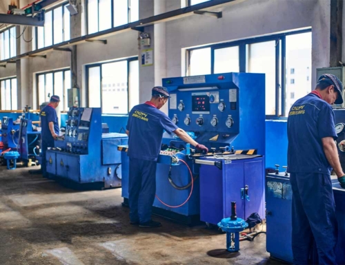
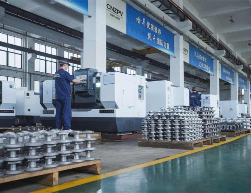
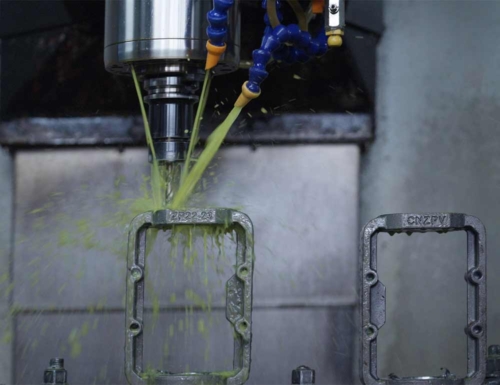
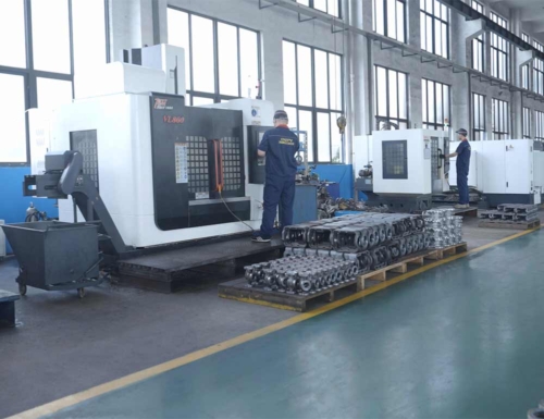
CNZPV (Zhipeng Valve Group) is a specialized company integrating design and manufacturing. Here, you can explore products and updates on leading valve lines (including lined valves and metal valves) and actuators, as well as access professional solutions for industrial corrosion and fluid control challenges. Feel free to pose questions—our team of engineers with 30+ years of experience will provide expert answers and deliver optimal control valve solutions. We welcome you to join our partnership network.