In process industries such as oil & gas, chemical, and power generation, control valves play a pivotal role in regulating fluid flow, pressure, temperature, and level to ensure stable and efficient operation of production processes. A sudden “not responding” fault of control valves in the field can lead to process deviations, production interruptions, and even potential safety hazards. This field troubleshooting guide is designed to help on-site maintenance engineers and operators systematically diagnose and resolve control valve non-response issues, with a focus on practicality, operability, and professional accuracy.
1. Overview of Control Valve Non-Response Faults
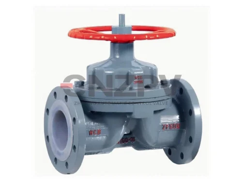
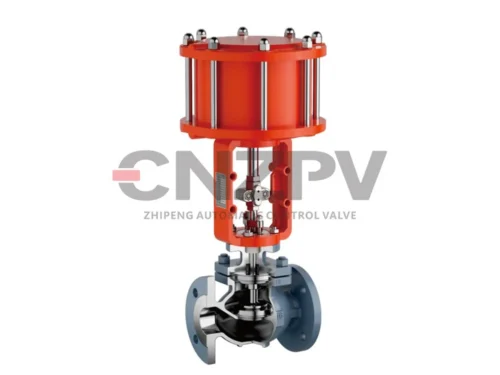
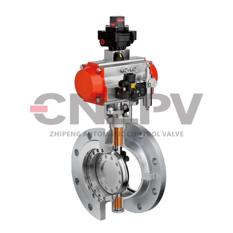
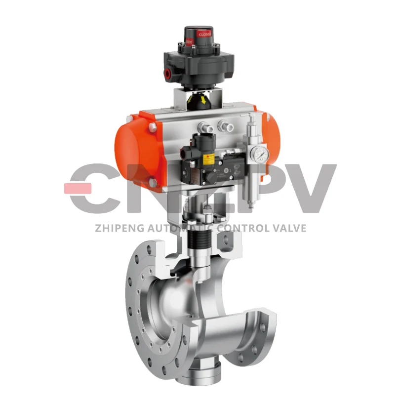
Control valve non-response refers to the phenomenon that the valve fails to perform corresponding opening or closing actions as required when receiving control signals (pneumatic, electric, or hydraulic) from the distributed control system (DCS) or programmable logic controller (PLC). According to the power source type, control valves are mainly divided into pneumatic control valves, electric control valves, and hydraulic control valves, and the causes of non-response faults vary significantly due to different drive principles. Before troubleshooting, it is necessary to first confirm the valve type, signal type (4-20mA analog signal, digital signal, etc.), and the specific working conditions (medium, pressure, temperature, flow rate) to narrow down the fault range.
Key pre-check points before troubleshooting: ① Confirm whether the DCS/PLC has issued a valid control signal; ② Check the on-site power supply (for electric valves) or air supply (for pneumatic valves) status; ③ Observe whether there are obvious external damages (such as valve body leakage, actuator deformation, pipeline blockage);④ Understand the recent maintenance history of the valve (whether it has been disassembled, calibrated, or replaced with parts).
2. Systematic Troubleshooting Steps
Troubleshooting of control valve non-response should follow the principle of “from simple to complex, from external to internal, from signal to mechanism” to avoid blind disassembly and reduce troubleshooting time. The specific steps are as follows:
2.1 Verify the Control Signal
The first step is to confirm whether the problem lies in the signal transmission link. For analog signal-controlled valves (such as 4-20mA), use a multimeter or signal generator to detect: ① Whether the output signal of the DCS/PLC module is normal (for example, when the set value is adjusted, the signal changes linearly between 4-20mA); ② Whether the signal at the on-site valve positioner (for pneumatic valves) or actuator terminal (for electric valves) is consistent with the DCS output signal. If there is no signal or the signal is unstable, the fault may be in the signal cable (open circuit, short circuit, poor contact) or the DCS/PLC module. For digital signal-controlled valves (such as PROFINET, HART protocol), use a dedicated communicator to check the communication status and whether there is an error code.
2.2 Check the Power/Air Supply
Power/air supply is the energy source for the control valve to operate, and its abnormality is one of the common causes of non-response.
- Pneumatic control valves: Check the air supply pressure (usually 0.4-0.6MPa) with a pressure gauge. If the pressure is too low or there is no air supply, check the air compressor, air filter, pressure regulator, and air pipeline (whether there is blockage, leakage, or freezing in winter). At the same time, check whether the air filter is clogged with water and oil, which may cause the valve positioner or actuator to fail to work normally.
- Electric control valves: Check whether the power supply (AC220V, DC24V, etc.) is normal with a multimeter. Check the power cable for loose terminals, short circuits, or burnout. For frequency conversion-controlled electric valves, also check the output status of the frequency converter.
- Hydraulic control valves: Check the hydraulic oil level, oil pressure, and hydraulic pump operation status. Check for oil leakage in the hydraulic pipeline and whether the one-way valve, relief valve, and other components are blocked or faulty.
2.3 Inspect the Actuator
The actuator is responsible for converting the control signal into mechanical action. If the signal and power/air supply are normal, the fault is likely in the actuator.
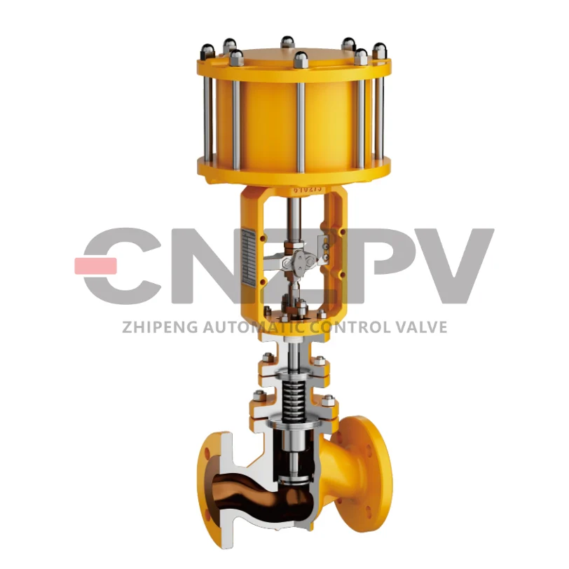
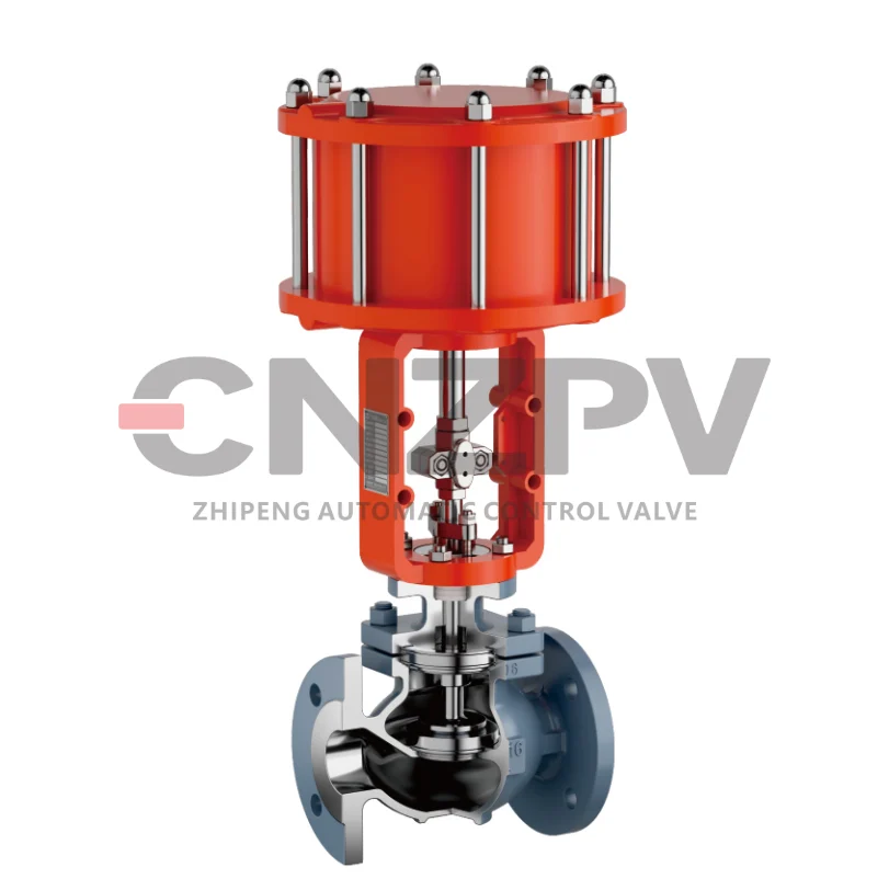
- Pneumatic actuators (diaphragm type, piston type): ① For diaphragm actuators, check whether the diaphragm is damaged or leaking (if damaged, the air pressure cannot drive the valve core to move); ② For piston actuators, check whether the piston seal is worn, resulting in air leakage. You can manually operate the bypass valve of the actuator to observe whether the valve can move. If it can move manually, it indicates that the actuator has a fault.
- Electric actuators: ① Check whether the motor is running (listen to the sound) when receiving the control signal. If the motor is running but the valve does not move, it may be a fault in the gearbox (such as gear wear, jamming) or the coupling; ② If the motor does not run, check the motor winding (whether it is burned out) and the limit switch (whether it is stuck in the limit position, resulting in the motor not being powered on).
- Hydraulic actuators: Check whether the hydraulic cylinder is leaking oil, whether the piston rod is stuck, and whether the solenoid valve is working normally (use a multimeter to detect the solenoid valve coil voltage, and check whether the valve core is blocked).
2.4 Examine the Valve Body and Internal Components
If the above steps are normal but the valve still does not respond, the fault may be in the valve body or internal components. At this time, it is necessary to isolate the valve from the process system (close the front and rear cut-off valves, release the pressure) before disassembly and inspection.
- Valve core and valve seat jamming: This is a common fault in harsh working conditions. The medium contains impurities, coking, scaling, or the medium crystallizes, which can cause the valve core to be stuck with the valve seat. After disassembly, check the valve core and valve seat for wear, corrosion, or blockage, and clean or replace them if necessary.
- Valve stem damage: Check whether the valve stem is bent, broken, or worn. The damaged valve stem cannot transmit the mechanical action of the actuator to the valve core, resulting in non-response.
- Gasket or seal damage: If the gasket or seal inside the valve body is damaged, it may cause the medium to leak into the actuator, affecting the normal operation of the actuator. At the same time, check whether the valve bonnet is loose or leaking.
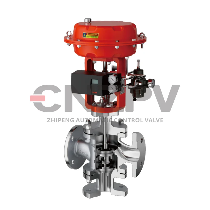
2.5 Calibrate the Valve Positioner (for Pneumatic Valves)
The valve positioner is a key component of the pneumatic control valve, which converts the electrical signal into a pneumatic signal to control the actuator. If the positioner is inaccurate or faulty, the valve may not respond to the signal. Use a signal generator to input a 4-20mA signal to the positioner, and check whether the output air pressure of the positioner changes linearly with the input signal. If not, calibrate the positioner (zero point and span calibration). If calibration is ineffective, check whether the positioner’s nozzle, baffle, or feedback rod is blocked or damaged.
3. Common Fault Causes and Corresponding Solutions
| Fault Cause | Corresponding Valve Type | Solution |
| Signal cable open circuit/short circuit | All types (electric/pneumatic with positioner) | Use a multimeter to test the cable continuity, replace the damaged cable, and re-crimp the terminals to ensure good contact. |
| Insufficient air supply pressure for pneumatic valve | Pneumatic control valve | Check the air compressor operation, adjust the pressure regulator to ensure the air supply pressure is 0.4-0.6MPa; clean the air filter and remove pipeline blockages. |
| Motor burnout of electric valve | Electric control valve | Check the motor winding with a multimeter, replace the burned-out motor; check the cause of motor burnout (such as overload, voltage instability) and eliminate it. |
| Diaphragm damage of pneumatic actuator | Pneumatic diaphragm control valve | Replace the diaphragm; check whether the medium is corrosive to the diaphragm and replace it with a diaphragm of appropriate material if necessary. |
| Valve core jamming due to medium scaling | All types | Disassemble the valve body, clean the valve core and valve seat; add a filter in front of the valve to prevent impurities from entering; for easily scaled media, take heat preservation or flushing measures. |
| Valve positioner zero point deviation | Pneumatic control valve with positioner | Use a signal generator to perform zero point and span calibration on the positioner; clean the positioner’s nozzle and baffle to ensure smooth air flow. |
| Hydraulic cylinder oil leakage | Hydraulic control valve | Replace the seal ring of the hydraulic cylinder; check the piston rod for wear and repair or replace it; tighten the oil pipeline connections to eliminate leakage. |
4.Safety Precautions for On-Site Troubleshooting

On-site troubleshooting of control valves involves process systems, power supplies, and pressure-bearing equipment, so safety must be prioritized:
1.Before troubleshooting, must apply for work permits (such as hot work permit, confined space work permit if necessary) and notify the operation team to isolate the process system (close front and rear cut-off valves, open the vent valve to release pressure) to prevent medium leakage and personal injury.
2.When detecting electrical signals or power supplies, use qualified electrical measuring tools, wear insulating gloves and insulating shoes to avoid electric shock.
3.For flammable, explosive, toxic, and corrosive media pipelines, after isolating the valve, perform gas detection and replacement to ensure the working environment is safe.
4.When manually operating the valve, do not use excessive force to avoid damaging the valve stem or actuator; operate slowly and observe the process parameters to prevent sudden changes in pressure or flow.
5.After troubleshooting, restore the system step by step, check for leaks, and confirm that the valve operates normally before handing over to the operation team.
5. Preventive Maintenance Suggestions
To reduce the occurrence of control valve non-response faults, regular preventive maintenance is essential:
- Establish a control valve maintenance file, record the maintenance history, replacement parts, and calibration data, and formulate a regular maintenance plan (monthly, quarterly, annual).
- Regularly inspect the power/air supply system: clean the air filter of pneumatic valves, check the air pipeline for leakage; check the electrical connections of electric valves for looseness, and test the motor insulation performance.
- Regularly calibrate the valve positioner and travel switch to ensure accurate signal conversion and reliable limit protection.
- For control valves in harsh working conditions (high temperature, high pressure, corrosive medium, containing impurities), shorten the maintenance cycle, regularly clean the valve body, and replace vulnerable parts (diaphragm, seal ring, valve core) in advance.
- Strengthen the training of on-site operators and maintenance personnel to improve their ability to judge and handle common faults, and avoid misoperation that causes valve damage.
Conclusion
The non-response fault of control valves in the process area is a common and critical problem that requires systematic and standardized troubleshooting. By following the steps of “verifying signal → checking power/air supply → inspecting actuator → examining valve body → calibrating positioner”, combined with the characteristics of different types of control valves, we can quickly locate the fault cause and take corresponding solutions. At the same time, strict adherence to safety precautions during on-site operations and the implementation of regular preventive maintenance can effectively reduce the occurrence of faults, ensure the stable operation of the process system, and improve production efficiency and safety.
For more professional technical guides on process control valves,or equipment maintenance and fault handling, stay tuned to CNZPV.We are a professional control valve manufacturer & Supplier with 30 years of expertise.